Keywords: Graphite Products, Graphite Crucible, Graphite Mold...
Keywords: Graphite Products, Graphite Crucible, Graphite Mold...
Titanium is widely used in the chemical machinery industry because of its excellent characteristics such as low density and corrosion resistance. With its good corrosion resistance, titanium alloy pump castings have gradually replaced stainless steel and other corrosion-resistant materials and are widely used in the chemical industry. The impeller as a key component of the centrifugal pump determines the mechanical properties and working efficiency of the pump, and its quality and dimensional accuracy requirements are very high. Impeller blades can be divided into two shapes, single curvature blades and double curvature blades, as shown in Figure 1.
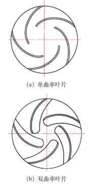
Figure 1
Titanium is a chemically active metal that easily reacts with a variety of elements and substances, so commonly used silicon-aluminum-based casting materials cannot be used to cast titanium and titanium alloys. At present, the most commonly used organic processing of titanium casting production graphite type process and investment precision casting process are two. The production of impeller castings using investment precision casting process requires the production of molds, molds, shells and other processes. The process is complicated, the production cycle is long, and the cost is high; using conventional machining of graphite-type casting double curvature impellers, often using model line In this way, the twisted blade part cannot be accurately manufactured, and it is difficult to meet the hydraulic performance of the centrifugal pump. This article mainly introduces a graphite-type casting process for double-curvature blade impellers. It produces high-quality, high-precision impeller castings. Through hydraulic performance testing, the various performances of the impeller fully meet the design requirements.
1. Graphite mold design
(1) Limitations of the conventional manufacturing process At present, the method of making the graphite type of the impeller runner core is:
① Each runner core of the impeller is made into a whole. ② "Core" is processed according to the mirror projection contour lines of the impeller flow channel and the front and rear cover plates (see Figure 2).
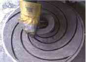
Figure 2 Impeller graphite core
③ Make the blade model according to the hydraulic flow lines of the front and rear cover plates of the impeller, and draw lines on the front and rear cover plates of the "core".
④Saw out the blade cavity according to the scribe line and sharpen it.
The above-mentioned manufacturing process has the following limitations:
① The blades are only considered by the hydraulic curves of the front and rear cover plates, and the hydraulic curves of the other sections of the blade are not considered, so the hydraulic model of the blade is not completely consistent with the design.
②The method of manual scribing has large deviation and uneven blades, which has a great impact on stability.
③Using a hand saw can only cut straight lines, which can meet the requirements for cylindrical blades, but it is very different for twisted blades.
④The blade cavity repaired by hand is often larger than the design, which results in the increase of the blade thickness and the efficiency of the pump.
(2) Difficulties in production and solutions The difficulties and solutions in the production of graphite molds with double curvature blades are as follows.
Difficult point one: processing of twisted blade graphite core. After the actual operation test on site, if the hydraulic model of the blade is to be processed accurately according to the hydraulic diagram, each blade interferes with each other during the processing, and there is no operability, so it causes great difficulties in the manufacture of the impeller core.
Solution: Separate the individual blades for processing, and then assemble them into a whole, as shown in Figure 3.
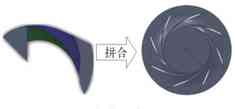
Figure 3 Twisted blade machining
Difficult point two: control of blade size accuracy. Impeller hydraulics affect the overall performance of the pump, and the accuracy of the blade hydraulic model is very important. The hydraulic surface of the hand-made blade is very poor in accuracy. The hydraulic model of the blade can only be corrected by the template. There are certain errors in the model itself, plus the randomness of the production staff, which often leads to the blade and the designed hydraulic model. The difference is large, which has a greater impact on the hydraulic performance of the pump. In addition, during the process of assembling the blade graphite core, due to the accumulation of errors, the final dimensional deviation will exceed the allowable range. Therefore, the blade dimensional accuracy must be effectively controlled.
Solution: The CNC machine tool is used to process the blades. The machining accuracy of the CNC machine tool can reach 0.02mm/300mm, and the consistency of each blade is very good, which can control the blade dimensional accuracy to the greatest extent.
Difficult point three: the inspection of the graphite core of the blade. It is difficult to accurately measure the hydraulic surface of the blade using conventional measurement and inspection methods. The blade has a hydraulic curved surface, and the curved surface is difficult to measure with conventional tools and measurement methods such as steel rulers and vernier calipers, and the measurement error is very large, so the actual accuracy of the impeller graphite core is lost.
Solution: Use a measuring instrument to perform an overall scan of the hydraulic surface of the blade. The scanned file is converted, and then the software is used to compare the scanned file with the designed three-dimensional model. The comparison result can accurately show the difference between each area of each surface of the blade, and display different errors in different colors. Using this method, the hydraulic surface of the produced blade can be accurately detected to evaluate the production effect.
2. Mold and casting manufacturing
(1) Mold design The impeller mold is shown in Figure 4.
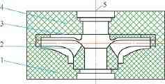
Figure 4 Impeller mold 1. Lower type 2. Impeller core 3. Back blade core 4. Upper type 5. Connect to runner
(2) Mold making Except for the impeller core, the remaining molds can be processed using an ordinary lathe.
The impeller core is precisely processed using a CNC machine tool, and the processing flow is as follows.
3D drawing: Use SolidWorks to draw a 3D drawing of the impeller product.
Shape design: design the three-dimensional shape of the impeller according to the casting process, and divide the core of the impeller into a single blade core.
NC programming: NC programming of the blade core pattern.
Machine tool processing: CNC machine tool processing graphite pattern, as shown in Figure 5.
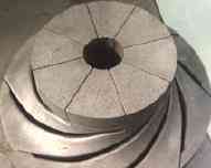
Figure 5 Graphite type of impeller core
(3) Casting inspection The upper, lower and back blade cores of the impeller can be measured and inspected using vernier calipers and samples.
The impeller core is processed by a CNC machine tool, and two pieces are extracted for three-dimensional full scanning. The scanning results are compared with the three-dimensional modeling drawings. After comparison, the average error between the graphite type of the blade and the designed three-dimensional pattern is within 0.1 mm, which fully meets the design requirements.
(4) Casting production After the graphite casting mold inspection is passed, vacuum degassing graphite mold, group casting, polishing and trimming of the impeller casting are carried out according to the relevant process.
(5) Quality inspection The castings have been tested by X-rays, and there are no obvious defects in the impeller castings, which meets the technical requirements for acceptance. The chemical composition and mechanical properties of castings meet the technical requirements. After passing the inspection, the castings are processed according to the product drawings.
3. Conclusion
(1) Using the method of separate processing and integral assembly, the graphite type of the double-curvature blade impeller can be successfully manufactured accurately.
(2) Using CNC precision machining, the blade core can be precisely processed to ensure the accuracy of the hydraulic surface of the impeller blade.
(3) The three-dimensional scanning detection method can be used to measure the size of irregular spatial curved surfaces and evaluate the detection results.
(4) Through the comparison of hydraulic performance tests, it can be concluded that the CNC precision-processed graphite-type impeller castings have blade hydraulic surfaces that are more in line with the design requirements than the hand-made graphite type; the hydraulic performance of the CNC-processed graphite-type impeller is higher than conventional production. The graphite impeller is closest to the design standard performance curve.
Previous None
Next Can you tell the difference between carbon materials and graphite materials?